คุณสมบัติ
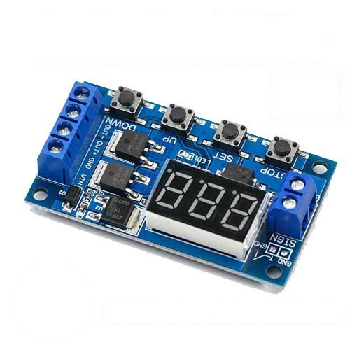
– แรงดันไฟฟ้า 5V – 36V
– ทริกเกอร์ระดับไฟฟ้าแรงสูง (3V ~ 24V)
– เอาต์พุต DC 5V ~ 36V ที่อุณหภูมิห้องกระแสต่อเนื่องคือ 15A กำลังไฟ 400W
– อุณหภูมิตัวอุปกรณ์ต่ำกว่าอุณหภูมิห้องกระแสสามารถสูงถึง 30A
– กระแสไฟฟ้าในขณะที่ทำงาน 50mA
– อุณหภูมิในการทำงาน -40 ℃ ~ 85 ℃
– ช่วงเวลาการหน่วง 0.1 วินาทีถึง 999 นาที
โหมดการทำงาน:
P1: สัญญาณทริกเกอร์เปิดเวลา “OP” แล้วตัดการเชื่อมต่อในเวลา “OP” ดังนี้:
P1.1: เมื่อส่งทริกเกอร์มาจะไม่ทำงาน
P1.2: เมื่อส่งทริกเกอร์มาเวลาจะถูกรีเซ็ต
P1.3: เมื่อส่งทริกเกอร์มาจะหยุดเวลา
P-2: เมื่อส่งทริกเกอร์มาจะปิดการทำงาน “CL” และจะเปิดการทำงาน “OP” แล้วตัดการเชื่อมต่อ
P3.1: เมื่อส่งทริกเกอร์มาเปิดการทำงาน “OP” และจะปิดการทำงาน “CL” และเมื่อหยุดส่งทริกเกอร์ จะทำงานตรารอบที่เราตั้งไว้ (“lop”)
P3.2: ไม่ต้องส่งทริกเกอร์มา แต่จะเปิดการทำงาน “OP”และจะปิดการทำงาน “CL” และรอบการทำงานจะทำตามที่ตั้งไว้ (“lop”)
P-4: เป็นโหมดการส่งสัญญาณ หากหยุดส่งทริกเกอร์จะเปิดการทำงาน “OP” และเมื่อส่งสัญญาณเข้ามาเวลาจะถูกรีเซต
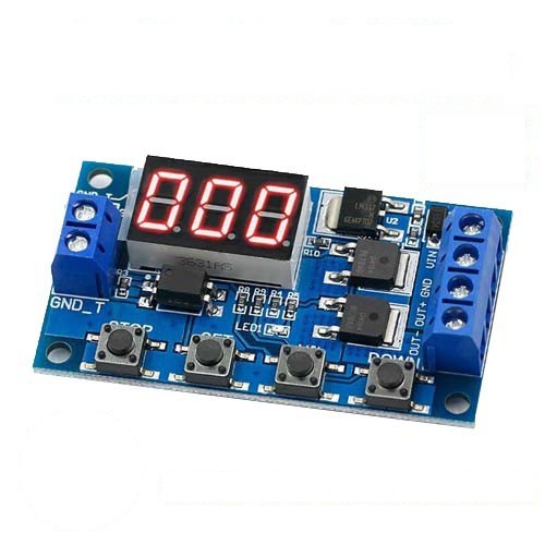
Product description
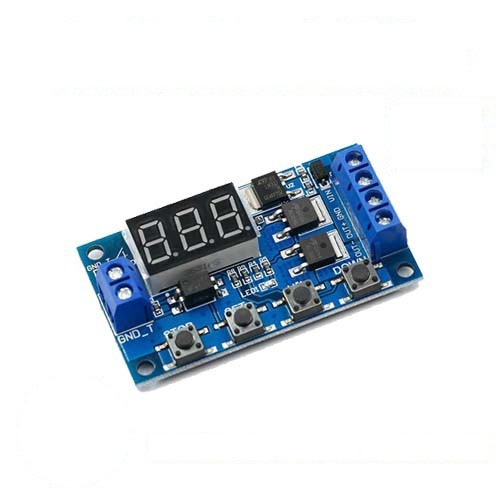
HW-516 DC 12V 24V Dual MOS LED Digital Time Delay Relay Trigger Cycle Timer Switch Circuit Board Timing Control Module DIY
Descriptions:
Operating mode:
P1: trigger signal the relay is on “OP” time and then disconnect; in the “OP” time as follows:
P1.1: signal is triggered again invalid
P1.2: signal is triggered again the clock is reset
P1.3: Signal trigger again relay off stop the clock;
P-2: trigger signal the relay off “CL” of time the relay on “OP” time and then disconnect relay;
P3.1: trigger signal the relay is turned on after the “OP” time the relay off “CL” time then the operation cycle if the trigger signal period the relay off stop the clock; the number of cycles ( “LOP “) can be set.
P3.2: without triggering signal the relay is on “OP” time the relay off “CL” time and has been cycling; frequency ( “LOP”) cycle can be set;
P-4: signal holding function. If there is a trigger signal timing is cleared the relay remains on; when the signal disappears after the timing “OP” time the relay is; if another signal during timing timing is cleared;
Pay attention:
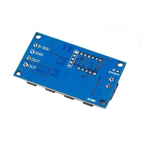
The module is an active output the output voltage equal to the input voltage.
2.’DC + ‘and’ load + ‘This is an internal short circuit of the poles but’ DC- ‘and’ load – ‘poles during use can not be shorted otherwise the load can not be controlled on and off which is equivalent load is been carrying electricity.
Timing range
0.1 seconds (min) to 999 minutes (max) continuously adjustable
How to choose the time range?
After setting the mode selection screen parameter value by a short press “STOP” button to select the time range;
XXX. decimal point in the unit place time range: 1 second to 999 seconds.
X decimal point in decade place Timing range: 0.1 seconds to 99.9 seconds
X. X. decimal full brightness Timing range: 1 minute to 999 minutes.
For example you want to set “OP” is 3.2 seconds then move the decimal point to decade place the digital display 03.2
Parameter description: “OP” – conduction time “CL” – off time “LOP” – the number of cycles (1-999 times “—” represents infinite loop).
These parameters are independent of each other but is shared by each mode. For example in P1.1 mode set the on-time “OP” is 5 seconds if you switch to P1.2 mode it’s “OP” will be 5 seconds too.
In the main interface (display 000) short press “SET” button will display “OP” ( “CL” “LOP”) and the corresponding time XXX;
Some parameters only mode “OP” (such as the mode P1.1 P1.2 P1.3) short press the “SET” key to display only the “OP” and the corresponding time;
Some models have parameters “OP” “CL” “LOP” (such as the mode P3.1 P3.2) short press “SET” button will display “OP” and the